This post describe how to install a 4 channel Relay board on a Raspberry Pi and how to control it with Domoticz.
With a relay you can control modules with needed a higher voltage than the Raspberry Pi, in my case a filterpump for the swimmingpool.
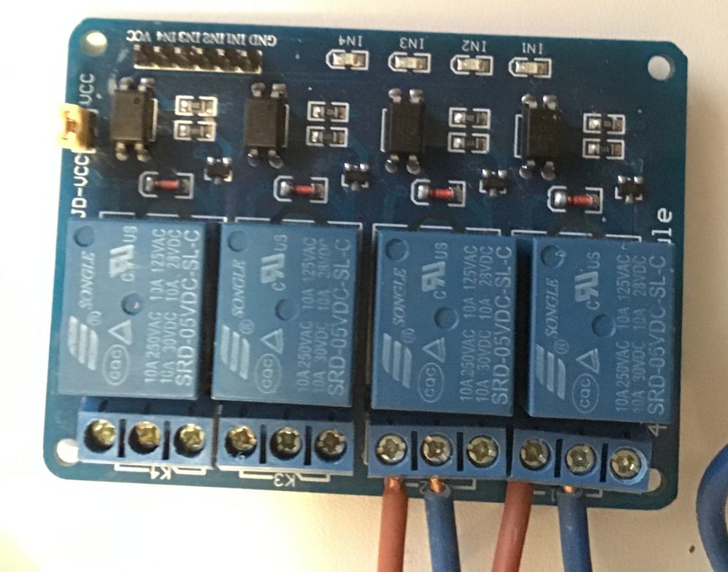
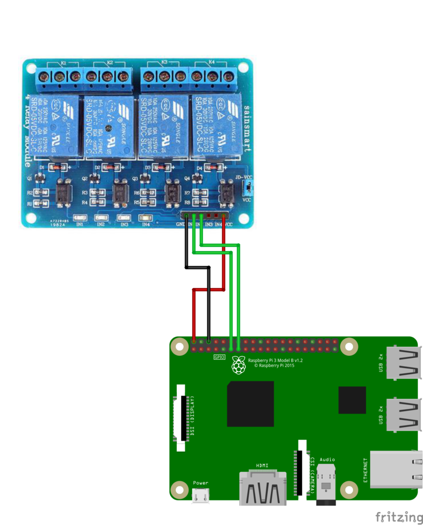
Step 1: Connect the relay to the Raspberry Pi
We need to connect with the female-female jumper wires the relay board to the Raspberry Pi. To see the explanation of each pin, goto the Raspberry GPIO explanation page. We use the following schema for the pins.
| Relay | Raspberry |
| VCC | PIN2 – 5V |
| IN1 | PIN11 (GPIO17) |
| IN2 | PIN13 (GPIO27) |
| GND | PIN GRND |
Step 2: Validate the working through the WiringPi gpio module
First check the installation of the WiringPi module with this command
gpio -vIf the result looks like ‘gpio: command not found’ we need to install the WiringPi Package with the command
sudo apt-get install wiringpiTo enable GPIO17 as type OUT, you can type the following command
gpio export 17 outNou the GPIO17 is exported as the OUT and the relay is switched on. Just play arround with the following commands:
gpio readall
# show the current states of all pins

gpio exports
# show all the current exported pins.
All the exported pins can read by Domoticz.
you can look here: http://wiringpi.com/the-gpio-utility/ for more information.
Step 3: Prepare the GPIO pins for Domoticz with sysfs
Accoring Domoticz the use of the wiringPi module is the ‘old’ way and the new way is Generic sysfs GPIO. If we want to export GPIO17 you can use the following command
echo 27 >> /sys/class/gpio/exportTo check if the pin is exported, use this command
ls /sys/class/gpioBy default the pins direction is IN. Just like the wiringPi module we can change the direction by echo out >> /sys/class/gpio/gpio27/direction.
However! as we noticed by de wiringPi, if we set the state to OUT the pin becomes active and the relay is turned on. We don’t want the ralay on by default so we need te set the direction to HIGH.
Also, we need to toggle the state of the GPIO Pin. By default Domoticz things the switch is on of the relay is off.
Use the following commands:
sudo sh -c "echo '1' >> /sys/class/gpio/gpio27/active_low"
echo high > /sys/class/gpio/gpio27/direction
Now we toggled the state and the relay is by default off. You can play arround with the following commands to turn on and off the relay.
echo 1 > /sys/class/gpio/gpio27/value
echo 0 > /sys/class/gpio/gpio27/value
Step 4: Enable the GPIO automatic after a reboot
We now know how we can enable a GPIO pin with wiringPi and sysfs. However, after a reboot all the pins are set in there default state (in). There are several ways, but my prefered way is with a own bashscript executed from rc.local.
Create a setGpio.sh script file
We add a setGpio.sh script file in our home directory. In this script we export GPIO17 and GPIO27 because we want to manage 2 relays in domoticz.
vim ~/setGpio.sh
#add the following code
#! /bin/bash

printf "Set GPIO"
printf "\n"

#relay pos1
echo 17 > /sys/class/gpio/export
sudo sh -c "echo '1' >> /sys/class/gpio/gpio17/active_low"
echo high > /sys/class/gpio/gpio17/direction

#relay pos2
echo 27 > /sys/class/gpio/export
sudo sh -c "echo '1' >> /sys/class/gpio/gpio27/active_low"
echo high > /sys/class/gpio/gpio27/direction
exit 0
make the file executable
chmod +x ~/scripts/setGpio.shExecute this script in the rc.local file
vim /etc/rc.local

#add at the end of the script and before exit 0 this line
/home/pi/setGpio.sh
save the file and trigger a reboot:
sudo reboot
After the reboot you can check your exported pins
gpio exports

#the result should look like
GPIO Pins exported:
  17: out  0  none
  27: out  0  none
If not, check your logfiles in /var/log (start with the bootlog: cat /var/log/boot.log
Step 4: Add switches in Domoticz
Now we can manage the relays we want 2 swichtes in Domoticz to toggle the state of the relais.
a) Add GPIO Hardware
In Setup -> Hardware add New hardware of the type ‘Generic sysfs GPIO’.
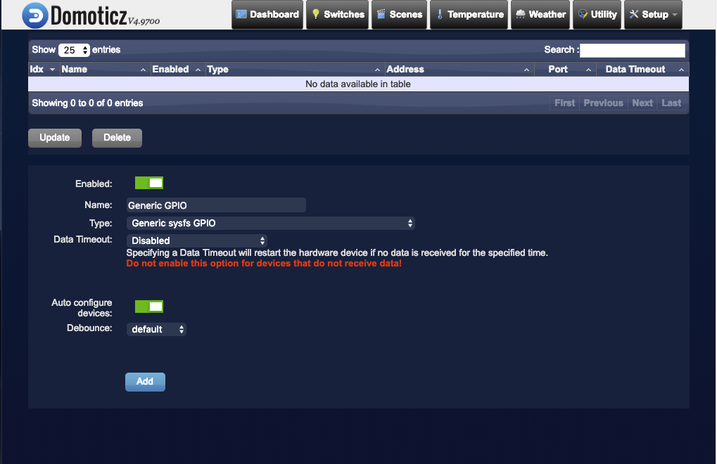
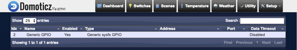
Click on ‘Add’. You should see a record like this.
b) Edit devices
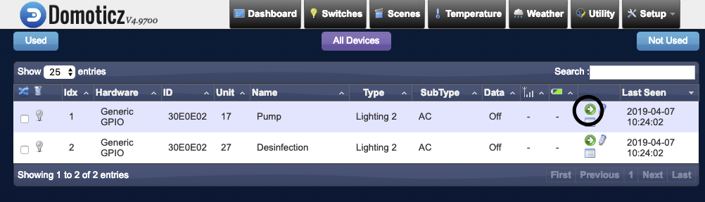
Goto Setup -> Devices. You see automatically the exported GPIO pins.
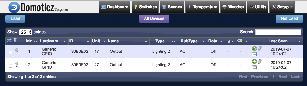
The bigger project for me is to automate my swimmingpool. So with one switch i want to enable the swimmingpool pump and with the other switch i want to enable the salt electrolysis.
I rename Idx1 (GPIO17) to Pump and Idx2 (GPIO27) to Desinfection by clicking on the pencil.
c) Enable switches
You can enable the switches in Domoticz by clicking on the green arrow of a device on the page ‘Setup -> Devices’.
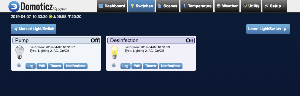
d) use the switches in domoticz
Go to the switches page in domoticz. Here you see the two added switches for the Pump and Desinfection. You can turn it on or off by clicking on the light bulb.